How to Draw Tangent to a Circle in Autocad
Intro. to Computers for Architecture Majors: § 3: Review of AutoCAD Commands
Instructor: M.S. Schmalz
AutoCAD Release 13 has a convenient interface that integrates drawing display, drawing and editing tools, and status information in an easy-to-use multi-window system based on the Microsoft WindowsTM operating system. In this section, we introduce you to the interface, and show how to perform simple AutoCAD commands. This section is organized as follows:
- 3.1. The AutoCAD Interface
3.2. File Commands and Device/Screen Setup
3.3. Graphics Objects and Drawing Commands
Section 3.1 contains an overview of the interface, and Section 3.2 overview the use of AutoCAD's device setup software. Concepts of graphics objects, drawing commands, and editing procedures are discussed in detail in Section 3.3.
3.1. The AutoCAD Interface.
On a Windows-equipped workstation or PC, AutoCAD is invoked by positioning your pointing device cursor (e.g., mouse arrow) over the icon that says "AutoCAD R14", then double-clicking the left mouse button.
The AutoCAD R14 interface has four salient regions, as shown in Figure 3.1 and explained below:
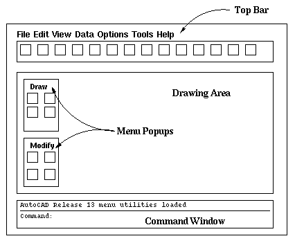
Figure 3.1. Schematic layout of AutoCAD interface.
Drawing Area. The large rectangular window in the center of your computer screen is where you enter and view drawings interactively.
Top Bar. The Top Bar, a narrow strip across the top of your screen, contains names of pull-down menus such as File, Edit, View, etc. that control various tools.
Command Window. This three- to five-line rectangular window at the bottom of your computer screen is the area where you can enter specific commands by typing on the keyboard. When you invoke commands from pull-down or clickable menus, the corresponding command text often appears in the Command Window.
Menu Popups. Many of AutoCAD's functions have been linked to visually explanatory icons that are grouped in several popup windows. The standard Microsoft Windows protocol applies to each window, for convenience. The icons can be activated by positioning your pointing device arrow over the appropriate icon, then clicking with the left mouse button.
Additionally, the top line of the window displays the file name of an active drawing.
3.2. File Commands and Device/Screen Setup.
AutoCAD has a convenient interface with DOS that readily faciliates file operations such as open, read, and write on AutoCAD drawings. We discuss salient operations on the File menu of the Top Bar portion of the screen, as follows.
New: Clears the Drawing Area and initializes a new AutoCAD drawing. Use this feature when starting a new project.
Open: Clears the Drawing Area and pops up a file selector widget, which prompts you for the name of the drawing you want to load. After you enter the drawing filename, the file is read in and the drawing appears in the Drawing Area.
Save: Stores on the specified disk a drawing that appears in the Drawing Area. If the drawing is larger than the drawing area, then the entire drawing is usually saved. An exception occurs when you specify a window or viewport (a partition of the drawing) and save that part of the drawing only. Such methods will be discussed later in the class.
Returning to the file-save procedure, if no disk drive has been specified, then AutoCAD will automatically save the drawing to the same disk as the AutoCAD program runs from (usually C: drive, or some other hard drive). In order to save your drawing to your floppy disk, you need to specify drive "A:".
Save As: Saves a drawing to disk and allows either a different drive or filename to be specified. On some of our projects, you will be able to Open a previous drawing, make some modifications, and use Save As to save the modified drawing under the new project filename.
Exit: This feature allows you to exit AutoCAD in an orderly fashion, and notifies you if there are unsaved drawings (i.e., ones you haven't already saved with the Save or Save As commands). If unsaved drawings exist, the file locator popup appears, so you can specify a filename and save the drawing(s).
Quit: Allows you to do a quick exit, without saving any drawings.
Additional Exercise: In Section 2, we talked about the interaction of applications programs with the operating system. Review the notes for that section, and ask yourself what processes might be occurring when AutoCAD opens or saves a drawing. Hint: One or two related questions could appear on a quiz.
Another problem with AutoCAD is setting up the screen when you are starting afresh with a new version of the software. This situation is not likely to occur when using University-supplied computers, but can be difficult for novice users working on home computers.
In summary, one should observe the following conventions when installing a legally registered copy of AutoCAD:
-
If you cannot find the printer driver for your particular type of printer, then call the AutoDesk help line and ask which one of the drivers supplied with AutoCAD best matches your printer. Beware of occasional anomalous results, as printer/driver mismatches can cause small features of drawings to appear in unpredictable ways.
-
Set up your graphics screen using the "CONFIG" command, by entering that command in the Command Window. You will be prompted for various parameters, which you should know before you start, for example,
- Resolution of your computer monitor, in pixels
- Type of mouse or pointing device (usually Logitech or Microsoft)
- Color scheme for screen set-up
A customary color scheme follows:
- Background: White
- Graphics Objects (Drawing Color): Black
- Crosshair Cursor: Red
- Menus: Standard black letters + beige background
Alternatively, a blue or black background with white drawing color may be useful, if you are accustomed to that color combination.
-
If you have a plotter attached to your computer, follow the installation directions, then select the appropriate plotter driver from the list of drivers supplied by AutoDesk. If your plotter is not listed (the vast majority are), then call the AutoDesk help line, as mentioned previously.
Do not attempt to configure the University workstations, as their configuration is set by the systems administrators for general use.
3.3. Graphics Objects and Drawing Commands.
AutoCAD has several types of graphics objects of interest to this class, including two-dimensional (2-D) primitives, dimensions, polylines, patterns/fills, and 3-D surfaces and solids. We begin our discussion of graphics primitives by discussing the drawing commands that make two-dimensional primitives appear on your computer screen.
Line. A line is the basic drawing tool for all of AutoCAD, and is defined as a line segment between a from-point or origin and a to-point or destination. Lines are drawn with the LINE command, which has the following salient options:
Continuation -- If a LINE command has been terminated, it can be resumed from the to-point of the most recent line segment drawn, even though other commands were used since drawing that line.
To activate the CONTINUE option, one enters the LINE command in the command window, or clicks on the LINE drawing icon, then enters a carriage return ({Enter} or {Return} key) when prompted for the from-point. A new line will begin at the most recent to-point.
Closure -- If a LINE command has been used to draw a connected sequence of line segments, then the CLOSURE option can be used to draw a line segment that has as its to-point the first from-point of the line sequence. Geometrically, this has the effect of closing the line figure to produce a polygon.
To activate the CLOSURE option, enter "C" when prompted for the to-point. Do not attempt to use the CLOSURE option if you have interrupted the drawing of a sequence of line segments by executing another command.
Undo -- If a LINE segment has been drawn erroneously and you want to erase it, enter LINE, then UNDO in the command window. The most recent segment drawn will be erased.
More complicated shapes are available, including circles and arcs, as follows.
Circle. A circle is formed in AutoCAD as a sequence of straight lines. Enough lines are used so that the viewer is tricked into believing that the smooth contour of a circle is present. This sleight-of-hand works because (a) the computer's display resolution limits the level of detail one can see when looking at the monitor and (b) the human visual system tends to smooth jagged curves to make them look more "natural" to the human brain. Hence, the detail that is present as small straight lines in a many-sided polygon is not visible under most conditions. One's visual system therefore infers that such high-resolution polygons are circles.
To draw a circle with AutoCAD, enter the CIRCLE command and choose one of the following options:
Center & Radius (CENRAD) -- With this option, you first click where you want the center point of the circle to be, then move the pointing device to establish the perimeter of the circle. The pointing device cursor and the center point delimit the circle's radius.
Center & Diameter (CENDIA) -- A variation on the CENRAD option first establishes the center point of the circle using the pointing device, then allows you to specify the circle's diameter by moving the pointing device cursor. Unfortunately, the line segment that visually indicates the diameter begins at the circle's center, rather than at the perimeter. Hence, the appearance of the circle can be confusing.
3-Point -- It is a well-known fact of geometry that three points define the perimeter of a circle. Hence, with the 3-point option, one merely clicks with the pointing device on each of the three points you want to choose, and a circle appears that passes through all three points.
2-Point -- The two-point circle is a variation on the 3-point option, and is activated similarly. This feature is used for drawing a circle when the diameter is known but the center is not. Hence, one specfies the endpoints of the circle's diameter, then moves the pointing device to establish the circle's perimeter.
Tangent, Tangent, & Radius (TTR) -- Given two lines as shown in Figure 5.2, the intersection of a circle with each line defines at least two points on the perimeter of the circle. The addition of a radius specification defines sufficient information to draw a circle tangent to both lines. In this option of the CIRCLE command, AutoCAD prompts you to click on the two lines, then specify the radius of the circle either by entering the radius value in the Command Window, or by moving the pointing device to arrange the circle to meet your requirements.
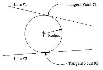
Figure 5.2. Configuration for tangent-tangent-radius
option of the CIRCLE command.
Arc. An arc is a contiguous partition of the perimeter of a circle. In AutoCAD, arcs are drawn with the ARC command, which has many options. The landmarks of an AutoCAD arc are the start and end points, the center of the arc, its length, and the angle subtended, as shown in Figure 5.3.
Here follow several commonly-used ARC command options:
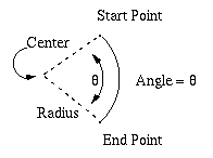
Figure 5.3. Landmarks of an arc.3-Point -- Similar to the 3-point circle, one defines an arc by clicking on points along its length.
Center, Start, End (CSE) -- One first clicks on the arc's center, then on each endpoint of the arc. This is useful for drawing nested arcs that have a common center point (e.g., the interior and exterior boundaries of curving sidewalks). There are numerous variations on this option (e.g., Start, Center, End or SCE; CES; etc.)
Center, Start, Angle (CSA) -- Occasionally, one needs to specify the angle an arc subtends, together with its center point and start or end point. Similar to the CSE option, there are numerous variations (e.g., Start, Angle, Center or SAC; SCA; etc.)
Start, End, Radius (SER) -- One first uses the pointing device to click on each end point of the arc. Then, one can specify the radius interactively by moving the pointing device and clicking when the desired radius is obtained.
Continuation -- This feature is similar to the Continuation option on the Line command. That is, one can draw "chained" arcs, where the from-point of the (i+1)-th arc is the to-point of the i-th arc. One does not have to enter the CONTIN option, but need only press the {Enter} key instead of clicking on the arc's from-point. This can also be used to draw a line from the last endpoint of an arc or chain of arcs, where the most recent arc's to-point becomes the line's from-point.
Ellipse. An ellipse can be thought of as an elongated circle. Ellipses have major and minor axes, as well as a center, as shown in Figure 5.4.
The following options pertain to the ELLIPSE command:
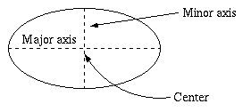
Figure 5.4. Landmarks of an ellipse.Endpoints & Rotation -- One clicks on the two endpoints of a given axis (major or minor), then moves the pointing device to rotate the ellipse to the desired position. If you know the rotation angle, you can enter in the Command Window instead.
Axis Endpoints + Center -- One can also click on the center of the ellipse, then click on an endpoint of each axis.
We have previously hinted that polygons were important in AutoCAD, when we said that circles are approximated by many-sided polygons. Also, we talked about producing an arbitrary polygon via the CLOSE option of the LINE command.
Polygon. As shown in Figure 5.5, there are two primary types of polygon: convex (all exterior angles greater than 180 degrees) and nonconvex. Convex polygons may be regular (all interior angles the same) or irregular (different angles).

Figure 5.5. Polygons: (a) convex, (b) regular, and (c) nonconvex.The following procedure is used with the POLYGON command:
Step 1. You will be prompted for the number of sides in the polygon -- enter this number as an integer on the command line, unless you are prompted to enter the number in an alphanumeric text slot in a dialog box. For example, a hexagon has six sides, and the maximum number of sides permitted by AutoCAD is 1,024.
Step 2. Pick the center of the polygon using the crosshair cursor, guided by your pointing device.
Step 3. You will be prompted to enter circumscribed or inscribed. A circumscribed polygon has a circle inside of the polygon, as shown in Figure 5.6a. An inscribed polygon is contained inside the circle, as shown in Figure 5.6b.
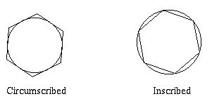
Figure 5.6. Circumscribed and inscribed polygons.Step 4. Enter the radius of the inscribing or circumscribing circle, per the prompt.
The polygon will appear in the Drawing Window, and you can rotate it using the pointing device. In some cases, Step 4 can be performed with the pointing device, with which one can establish the polygon size interactively. Additionally, the "E" option of the POLYGON command allows you to establish an edge of the polygon, versus the center (per Step 2). This is useful when aligning a polygon with an existing line.
Another interesting graphics primitive are tori (plural of torus), which AutoCAD calls "doughnuts".
Definition. A doughnut is a filled circle or ring, as shown in Figure 5.7a. The fill material is determined by the FILL and HATCH commands, which we will review later in this class.
Command: DOUGHNUT or DONUT.
Options: Solid circle (per Figure 5.7a), ring with solid fill (Figure 5.7a), figured or pattern fill (Figure 5.7b,c), or ring filled with radial lines (Figure 5.7d).
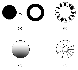
Figure 5.7. Doughnuts (a) permissible configurations, (b) ring with pattern fill,
(c) filled with solid or pattern, and (d) filled with radial lines.
This concludes our discussion of graphics primitives. We next examine the manipulation of AutoCAD graphics and text objects.
Copyright © 1997 by Mark S. Schmalz
All rights reserved, except for viewing or printing by UF faculty
or students registered for this class.
Source: https://johnstonewithile.blogspot.com/2022/06/drawing-area-in-autocad-definition.html
0 Response to "How to Draw Tangent to a Circle in Autocad"
Post a Comment